


Seach
The family-owned company Flowrox Oy in Lappeenranta manufactures flow regulating and control devices for industrial use. The company needed to replace the old machine that was used to make holes in the hose valve flange with a new one. Comatec Group’s subsidiary Insinööritoimisto Metso designed a new device that brought significant advantages compared to the previous one.
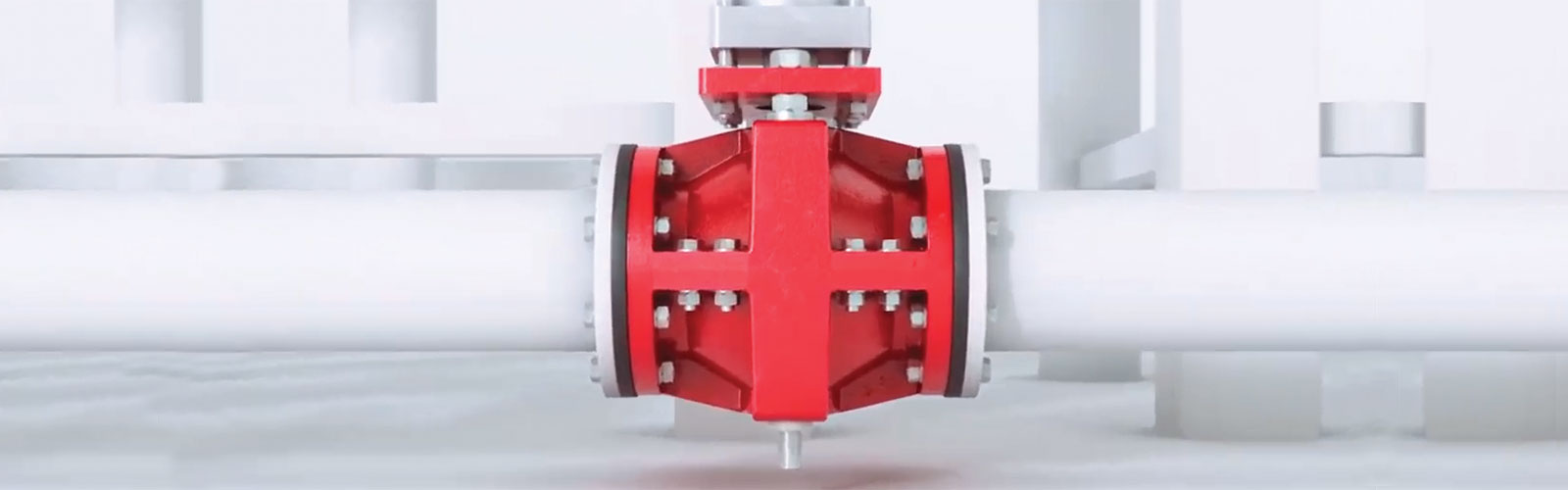
Hose valve assembled on piping. If the holes of the flange and the tube flange don’t align installation is not possible.
Flowrox has over 40 years of experience in elastomer technology relating to industrial valves, pumps and systems. Flowrox’s products are environmentally friendly and cost efficient solutions for demanding shutdown, adjustment and pumping uses.
They are suited for locking and regulation applications that are used to process erosive and corrosive sludges, powders and coarse substances. The hose valve structure includes three parts: the valve hose, the body and an actuator. The valve structure and hose material are customized according to the customer’s process environment.
The hose itself has a hose part and flanges at both ends. The flanges have holes that fit into the tube’s matching holes for installation purposes. If the holes of the hose and the tube don’t align, installation is not possible. Because of this, it is of utmost importance that the perforating machine works flawlessly.
The perforation of one hose is now 16 seconds faster. The number of valve hoses manufactured each year amounts to 18.300, so this saves a lot of time. At the moment, it takes 3.9 minutes to perforate one hose. However, the new machine’s best characteristic is reliability of operation.
“We had an old machine that was at the end of its life cycle. We couldn’t really get spare parts for the old machine, it didn’t function reliably anymore and we needed to replace it with a new, modern machine,” says Flowrox’s Sourcing and Procurement Manager Toni Turkkila about the assignment’s background.
“We chose Insinööritoimisto Metso to be our design partner in this project through a call for tenders. We have cooperated with them for a long time in designing our products, so we believed the cooperation would be flexible also in this case. They already know us and our products, and they know how to use this machine. They were located close by, and of course, price was one factor in the call for tenders,” says Toni Turkkila.
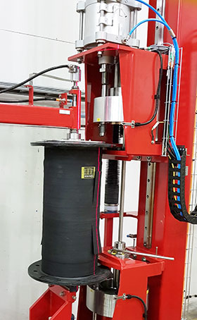
Insinööritoimisto Metso Oy designed a hose valve flange perforating machine for Flowrox on a turnkey basis.
“The planning work involved the design of mechanical, electronic and pneumatic parts. We also carried out installation supervision of the mechanics. For electrical contracting, we requested quotations and monitored electrical installation work. The project also included logic programming, implementation and user training, says Insinööritoimisto Metso’s Managing Director, Esko Seppänen.
“Our mechanical designers started planning from zero. We planned the machine, its movements and its structures exactly as specified in the starting values.”
The electrical, automation and application design was started once the mechanics plan created using Solidworks had
been completed and saved into the Flowrox system. The circuit diagram was created with Autocad. The application design, as well as the user interface, was realised via Siemens’ TIA portal. The control panel is operated with a touch screen and was built as an HMI solution that can be implemented exactly as desired.
“Application design played a major role in the planning. Nowadays, it can be combined with machine safety issues. This way, it can be controlled with the same system,” says Engineering Manager Antti Lautamies.
The movement control of the hose perforating machine consists of four servo shafts. Every shaft is controlled by a servomotor. In use the shafts are run to the hole’s perforation location according to the table. Feedback has been implemented using absolute encoders.
Regular and safety logic have been combined into the same control device. This makes planning and implementation easier. It is an integrated and efficient method for controlling motors, for example, when a certain process safety level is required.
Safety messages are transferred to the frequency converters through a bus. This way, emergency stops and the like can be handled without a relay-based emergency stop system. The system automatically detects disturbances or faults that require stopping the machine. Torque limits, for example, allow the machine to detect objects that might get between the shaft. In this kind of situation, the safety logic stops the machine.
“When safety and control are combined into the same control logic, fault situations are easier to solve with diagnostics. The fault is very easy to locate,” says Antti.
“Servo shafts are controlled by servo control devices that have been built with the Siemens S120 servo control system. This has been connected to the control logic with a Profinet fieldbus. Safety stops are transferred through the Profinet bus via Profisafe messages.
The machine contains, for example, one safety door and four emergency stop buttons. The door only opens when the process has been halted in a safe mode. At the same time, all four servo shafts are stopped, which means their accidental start is prevented. That is the largest risk factor of these machines, when we look at accident statistics,” Antti concludes.
A Significant improvement from the previous similar machine is that we solved a structural problem, and the holes are created in both ends of the hose at the same time. This way, their location is exactly the same on both flanges, which improves the quality of the hose valve significantly.
Holes in hose valves of different sizes are not identical. Because of this, the machine includes a cassette with six die cutters of different sizes. The standard defines the required hole size according to the size of the hose. The cassette moves to the right location based on the values given by the user in the user interface. A tie rod ensures that both hose ends have the correct die cutter, at the right location.
“The device is also twice as fast, because it processes both sides simultaneously, automatically and independently. It doesn’t need to be used manually,” Esko says.
“The perforation works safely in a closed space. No one needs to work close to the machine, and the operating safety is improved in this way.
The safety logic monitors the door and makes sure it is closed and acknowledged. It is impossible to open the door bypassing the safety logic. “The device is completely fool-proof from the security point of view,” Antti says.
“User training was very easy on both instructor and students, thanks to a user-friendly control system,” says Antti, who was responsible for training the users.
“I had built a very simple user interface, so the user training didn’t take long.” The user interface has very clear options. The operator’s console has a few buttons, and the entire layout is user-friendly. Anyone is able to learn quickly how to operate the machine.
“The holes perforated in hose flanges are specified in the valve standard according to hose size. There are over a thousand of them. They have all been pre-entered into the machine’s control system. All the shaft values and parameters are predefined. The user only needs to enter the correct table value and press a button. The machine will automatically perforate the right number of holes at the correct locations.”
“We were hoping to get a new machine as quickly as possible, because the old machine was already living on borrowed time. We didn’t expect the new machine to be a copy of the old one, but instead something new and more efficient. Now we have a machine that corresponds to today’s requirements. We got what we were looking for. The machine is now in use and still under development,” concludes Toni Turkkila.
TEXT: Taina Syrjänen
PHOTOS: Esko Seppänen and Flowrox Oy